Contour Optimization
Important
When using a robot with external axes, such as a rotary tilt table, ensure that the base coordinate system is correctly set and linked to the last axis of the table to guarantee correct motion generation.
See also Initializing the base with external axes.
In order to successfully carry out contour optimization, it is initially necessary to create the scene and define the scope of the program. This involves defining all the points required for the process, which serve as the basis for optimization.
If you have any questions or encounter any challenges during these steps, we recommend consulting the comprehensive KUKA.Sim Help. There you will find numerous explanations and detailed workflows to assist you with the procedure.
In this guide, we explain the steps for optimizing contours in your program. To gain a better understanding of contours, please read the relevant documentation first.
Contour Types
There are 3 different contour types:
These contour types will be used to describe different process operations. Further information about contour types and their functionalities can be found here.
Creating Contours
Contours can be easily created using the context menu or the statement menu of the program editor.
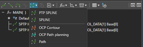
Statement menu in program editor from KUKA
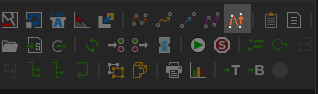
Statement menu from program editor from Visual Components
Statement Properties
As soon as a contour has been created and selected, the contour’s statement properties appear.
Program Optimization Settings
Once the contours have been defined, you can begin optimization. Various parameters can be adjusted to speed up the calculation or increase accuracy.
- The default settings usually deliver good results in a reasonable amount of time.
- If a faster or more precise calculation is required, you can adjust the options in the Program Optimization Settings.
Start the Contour Optimization
There are 4 different ways to start a contour optimization:
- Optimize single contour - starts optimization directly for the selected contours from the context menu. If the optimization assistant is already open, it switches to the single-contour mode and selects those contours for review instead.
- Optimize contours in relation - opens the Optimization Assistant and displays the selected contours as a task.
- Program Optimization - the Optimization Assistant displays all possible tasks in the selected program that can be optimized.
- Optimize single & connect - opens the optimization assistant from the context menu in the corresponding mode and applies the selected contours in selection order. At least two contours in the same scope are required.
The first two options can be easily started via the context menu. The program optimization will be started via the Optimization Assistent.
Operation mode and selection in the optimization assistant
The assistant lets you choose between Optimize selected program, Optimize single contours and Optimize single & connect. Changing the operation mode rebuilds the task list and resets your selection and connection order.
Program changes and robot changes also refresh the task list automatically and reset your selection, including the connection order. The selected operation mode stays active. Select the tasks again and check their order. The start button is disabled during a refresh and until a valid selection is available.
Optimize and connect selected contours
Select the contours in the desired order and choose Optimize single & connect from the context menu, or select this mode directly in the assistant. The context-menu action uses the same icon as individual contour optimization and applies your initial selection. Other contours remain available for selection in the task list.
Selected contours appear as a consecutively numbered block at the top of the task list. Use the ↑ / ↓ buttons on each row to change their connection order. Newly selected contours are appended to this block, including contours that you deselect and select again. Selecting a contour scrolls the view to its new position. Above the start button, the assistant displays the selection hint, connection sequence, and number of selected contours and connections.
Review the order and optimization settings, select at least two contours from the same scope, then start the calculation. The displayed order determines both the generated contour order and their connections. Connections use the current collision-free planning settings.
All selected contours are optimized individually and written back as new contours at the end of their shared scope. After all results have been received, collision-free connections are planned from the end of each generated contour to the start of the next one, including exit and entry motions.
For example, with four contours, the generated sequence is Contour 1 → Connection 1–2 → Contour 2 → Connection 2–3 → Contour 3 → Connection 3–4 → Contour 4. The order follows selection order, not the original program order. The original contours are retained.
The first optimization solution is used for each contour. Changing a contour solution keeps its generated connections and adds (Not Valid) to the names of paths that no longer match the selected solutions. Switching both connected contours back to the solutions used for those paths removes the suffix.
When the selected contour has generated connections, its property view shows Recalculate connections. This recalculates its incoming and outgoing connections using the currently selected solutions of both endpoints. Successful results update the existing path statements in place. Deleted path statements are recreated between their contours, even if all paths for the selected contour were deleted. Deleting or dissolving a contour removes its connection links from both endpoints; those connections are no longer regenerated. Old paths are retained until new results are available; failed or cancelled requests leave their paths and validity markings unchanged. Connection tracking, like the available optimization solutions, applies to the current session.
If a contour cannot be optimized, processing continues for the remaining contours. Connections are planned only for contours that are immediately adjacent in the chosen order and were both optimized successfully. Failed contours are not bridged by a connection. For example, if contour 2 fails in the sequence 1 → 2 → 3 → 4, connection 3 → 4 is still planned, but neither 1 → 2, 2 → 3, nor 1 → 3 is planned. Errors are collected and reported at the end.
When no connection is found and no path statement exists for that pair, a placeholder path statement containing the requested start and goal is inserted between the contours and marked (Not Valid). It is linked to both contours so that Recalculate connections can retry it. Switching solutions back does not validate this placeholder; only successful planning removes its suffix. Previously generated paths are retained on failed retries. If planning fails or is cancelled, the sequence may remain incomplete.
Calculation and Solutions
Provided that the backend is correctly connected, a calculation should now start. This also checks whether the selected robot has kinematics that we support (more information here). The duration of this calculation depends on the complexity of the program and the scene. You will then receive your results, separated by a HALT statement at the end of your program.
If you have any questions or problems, please do not hesitate to contact our support. You can find our contact details on our website. We wish you every success with your program optimization!