FAQ
FAQ – Frequently asked questions and troubleshooting
If you encounter problems, first check
- Which licence version is currently active?
- Is the byte robotics OCP plugin activated and functional?
- What is the current available computer performance?
Where can I find the hardware key in KUKA.Sim?
Please start KUKA.Sim and navigate to File → Options → Add On → byte Robotics - Optimized Collisionfree Pathplanning. If necessary, deactivate the OCP plug-in and then reactivate it. This will ensure that the hardware key is recognised and integrated correctly.
Where can I find the log files?
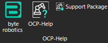
If you encounter any issues, you can use the Support-Package to provide more detailed information to the development team.
Please send us the ZIP file you created.
Error message: „No valid Start-States“
The following entry may appear in the log:
[2025-01-27 08:37:03.123] [info] Start connecting joints..
[2025-01-27 08:37:03.125] [info] Start Config: 5.49127deg, -34.6759deg, 90deg, 0deg, 0deg, 0deg
[2025-01-27 08:37:03.125] [info] Goal Config: 73.9641deg, -48.507deg, 143.281deg, 0deg, 0deg, 172.781deg
[2025-01-27 08:37:03.725] [info] Start "0.0958408 -0.605209 1.5708 0 0 0 " is invalid, sorted out.
[2025-01-27 08:37:03.725] [info] ==Last collision was between "PO426_VA_1X1_L0L_1BK" and "Kamerakopf_R01"==
[2025-01-27 08:37:03.725] [err] No valid Start-States in the Problem Definition!
[2025-01-27 08:37:03.725] [warn] goal or start invalid
This message indicates that one of the defined positions (start or goal position) is already causing a collision – in this case between the objects „PO426_VA_1X1_L0L_1BK“ and „Kamerakopf_R01“. This warning also appears in the KUKA.Sim output window.
Recommended troubleshooting steps:
- Activate collision checking in KUKA.Sim. Please note that increased check depth slows down the simulation. Therefore, deactivate this check again after verification.
- In the OCP TOOLS tab, enable the Enable Detectors option. This will make collisions visible in the simulation window.
- Pay attention to the minimum clearance (specified in mm), which should ideally be greater than 0. If the minimum clearance is too large, it can slow down the calculation unnecessarily.
- There must be at least two collision detectors under Edit Detectors:
Robot Name - Process + SupportRobot Name - Support Additional
If these are missing, click Update lists to update the detectors. Please note that this will overwrite existing lists.
- Adjust the A and B lists via Edit Detectors as follows:
- A list: All components that belong to the robot
- B list: All components with which a collision is possible Remove problematic parts from these lists if necessary. Note: The robot base is excluded from the collision check by default.
- Set the Termination Condition to
TerminationByFactorOptimizeand set the factor to 2, for example. A higher factor usually results in better paths, but increases the calculation time.
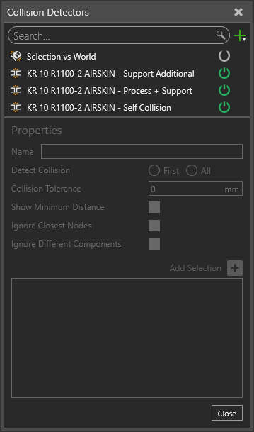
Collision detection – example view
‘Safety Cartesian Space’ - Safety spheres
- Does the entry ‘Safety Cartesian Space’ appear in the log? This indicates that KUKA SafeOperation is being used to map safety zones such as cell, work and protection areas in complex environments. Such restrictions must be taken into account during path planning.
- We currently recommend hiding the safety spheres, as they can otherwise cause collisions between the spheres and the robot. Improvements will be introduced in future updates.
Alternative approach:
Many users instead configure virtual walls around the robot, while the actual safety configuration is done exclusively on the robot itself.
Error message: ‘Could not connect backend – stream removed’
- If the byte robotics logo is not displayed in the taskbar or system tray, please check in Options whether the settings for the plug-in have been loaded and applied correctly.
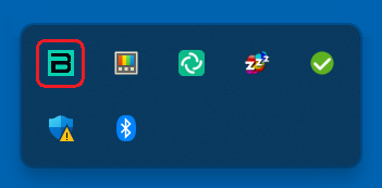
Backend tray icon
Polygons too large – CAD file too large
Error message:
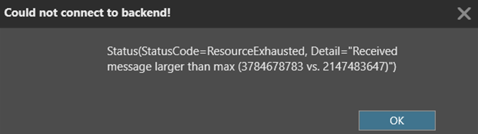
- Check the level of detail in your 3D model. If the file size exceeds 3 GB, it is recommended that you partially tessellate the model or remove unnecessary walls and components.
- To do this, open the Modeling tab, select the relevant component and adjust the tessellation level. Drag the slider all the way to the left to reduce the resolution. You can increase the level of detail again later if necessary.
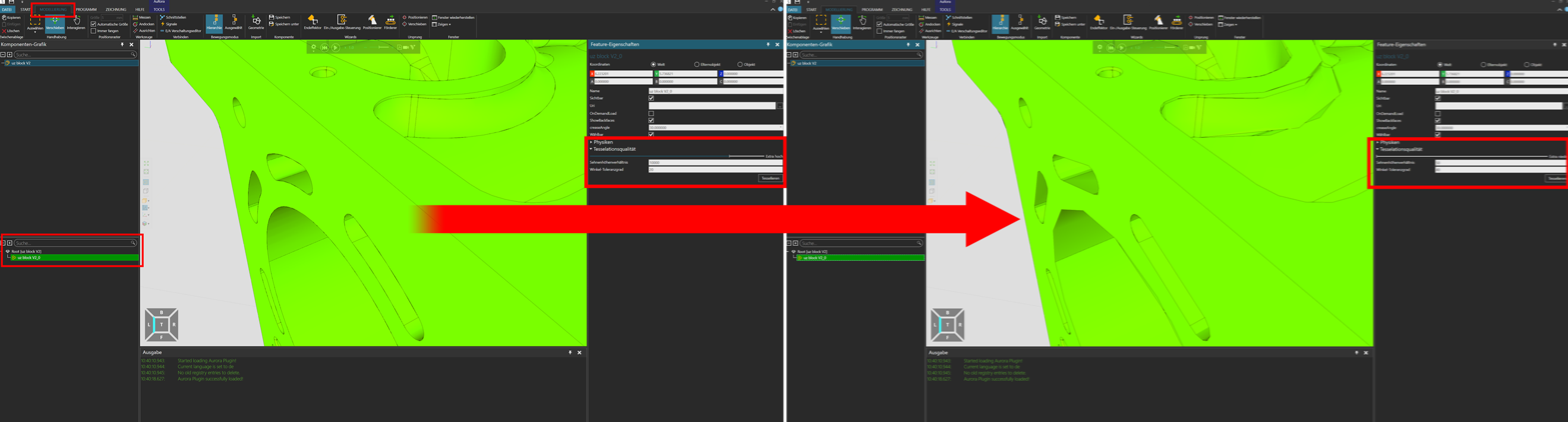
Tessellate – slider and button
Important notes:
- The tessellation slider only becomes active once you have clicked the Tessellate button.
- A lower level of detail sometimes makes components appear less intricate. Particularly detailed components are often product carriers or robot tools.
Collision Free Path Planning: Error message
Before planning, please carefully check that the starting position is free of self-collisions. Incorrect or colliding starting positions will result in planning failures.
Error message: ‘The server is not available’
This message indicates a problem with the backend connection. Please check the backend settings under File → Options → OCP Options → Connection Settings.
The status should show a green tick here. If this is not the case, use ‘Check’ to check whether the backend is accessible, or start it with ‘Start’.
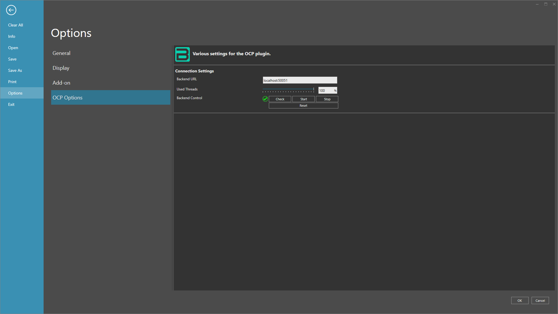
Backend options
If you need further assistance, please do not hesitate to contact our support team. Please provide the latest log files and a brief description of the problem you are experiencing. We are happy to help!
Thank you for using KUKA.Sim and the byte robotics OCP plugin. We wish you every success in your work!
If you have any further questions, please do not hesitate to contact us. You can find our contact details on our website.