Approach is expected.
Contours
Definition
Contours are used to better describe process sequences. A contour consists of 3 parts:
Approach(approach movements + first process point)Process(process movements)Depart(departure movements)
This makes it possible to optimize complex processes.
It defines which movements are intended for which tasks.
There are three different types of contours that can be used to describe processes.
Each of these types requires a movement command in Approach, while movement commands in Depart are optional in all contours.
The Process part must not contain any PTP commands, as contour optimization is not intended for this.
Further details are discussed below.
Open Contour
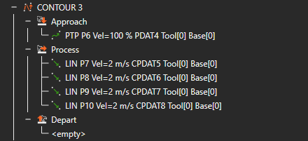
Open contours are the default setting when creating new contours. These are only used to optimize processes and do not require any special conditions to ensure their functionality.
Only a movement command in
Closed contour
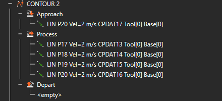
Closed contours are used to describe processes without explicit start and end points.
In order to interpret them correctly, the cartesian coordinates of the last movement command in
Approach must be identical to the cartesian coordinates of the last movement command in Process.
Point Contour
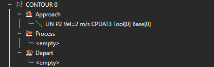
Point contours are used to describe processes that do not run along a path or edge.
Therefore, the
Process part is not taken into account. Only movement commands in the Approach part are required. Depart movements are not necessary, but are taken into account.
Contour Cheat Sheet
The following table explains which contour parts are required for which movement commands:
| Contour Type | Approach | Process | Depart |
|---|---|---|---|
| Open | x | x | o |
| Closed | x | x | o |
| Point | x | i | o |
x: necessary
o: optional
i: irrelevant
Tasks
A task consists of at least one contour. If, for example, there are motion commands between the contours, these are split into two separate tasks. This allows you to manually specify the separation of individual related subtasks.
If contours are located within folders, loops, or selective paths (e.g. if/switch), they are also treated as separate tasks. The last PTP motion command before a contour is used as the starting point, and the first one after the contour is used as the end point for optimization. If there are no motion commands or only one motion command before the contour, the contours within a task are optimized relative to each other as a loop.
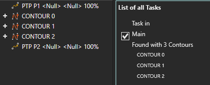
Beispiel einer Taskdefinition
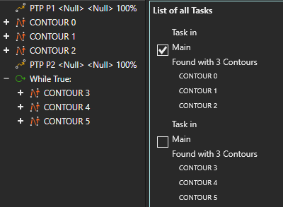
Beispiel einer Taskdefinition mit einer Schleife
Contour Properties
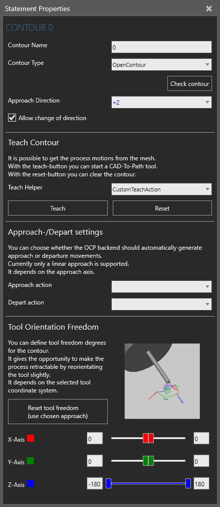
Contour properties
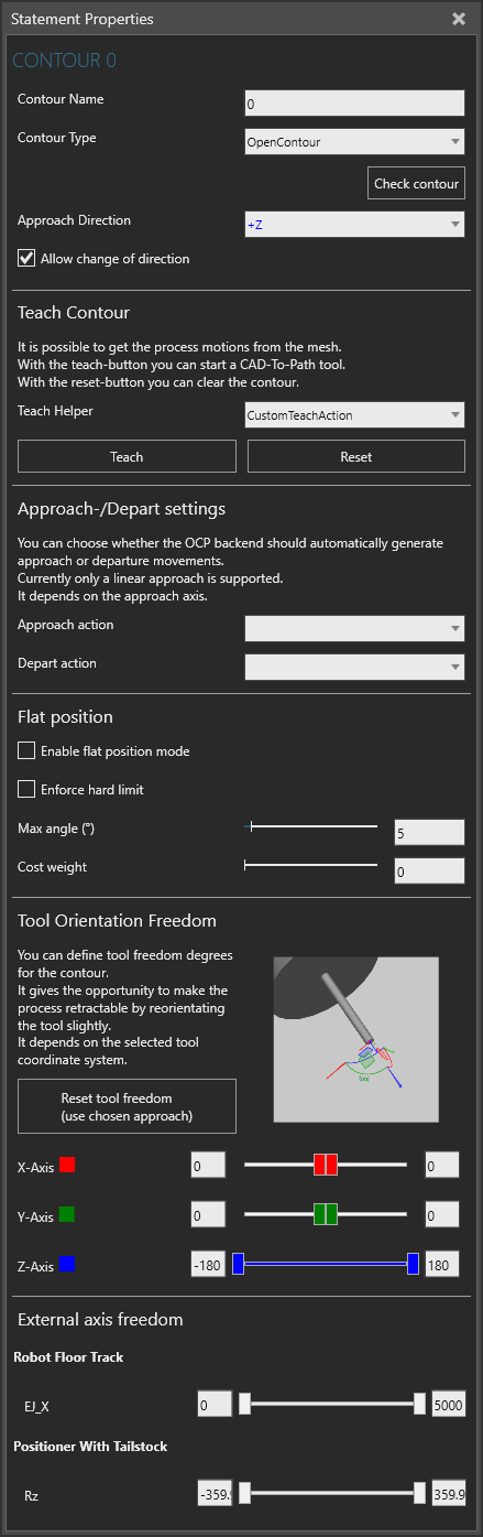
Contour properties with workpiece positioner
Basic settings
- The Contour Name can be customized as desired to increase clarity during planning. This has no further influence on optimization or other tools.
- The Contour Type can be selected:
- Closed Contour: The start and end points of a contour are the same. (e.g., cutting out a circle) With a closed contour, the software automatically decides at which point in the contour it will start processing it. However, no new points are added.
- Open Contour: The start and end points of a contour are different. (e.g.: cutting on a straight line) Here, the software can only decide in which direction it will follow the contour.
- Point Contour - a contour that contains only one point. (e.g.: spot welding)
- Check contour checks if the contour is valid. If not, an error message gets shown, which contains improvement ideas. Most of them can be applied by using the buttons of the error message. (Examples below)
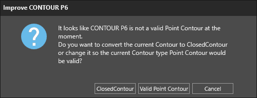
Point Contour Improvement Suggestion
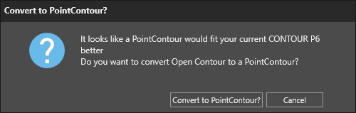
Open Contour Improvement Suggestion
- Approach Direction determines the direction, which is used to calculate the linear approach movement.
- Allow change of direction to switch the path direction automatically in backend for open and closed contours.
Teach Contour
- With the Teach Contour tool, contours can be selected directly from the CAD data of an object.
- Reset resets the contour. This means that all Statements in the contour are removed, so the contour is completely empty.
- Teaching of a contour is only possible, when only one contour is selected.
Approach/Departure Settings
- Under Approach-/Depart settings, you can select the actions or subroutines that will be executed during the approach or departure. For example, you can activate or deactivate a welding torch. To do this, create a new subroutine in the program editor and define all the necessary signals and commands there.
- When defining subroutines, ensure that there are no calls to other routines that could lead to a loop.
- The respective actions can be specified separately for approach and departure movements.
Flat position
- If a workpiece positioner is connected to the robot, options for the Flat position will be displayed.
- The desired flat position can be enabled or disabled.
- Hard limits can be enforced.
- A desired maximum angle can be defined.
- Manipulating the cost factor forces the vertical position of the robot tool; at high values, this can result in the robot movements no longer being optimal.
Degrees of Freedom
- With Tool Orientation Freedom, the degrees of freedom of the tool are defined for the contour.
- Reset tool freedom (use chosen approach) sets the three axes so that the chosen Approach Direction covers the range from -180° to 180°, and the other two axes are each set to 0.0.
- X,Y,Z - Axis allow individual freedom to be set for each direction, so that tool alignment can be accounted for.
- Absolute degrees of freedom can also be defined for the present external axis under External axis freedom.
Info
Please note that selecting more than three degrees of freedom expands the search space and the range of possible solutions. This may cause calculations to take longer. There may be combinations of settings that do not yield a solution when many degrees of freedom are selected. You can adjust the settings at any time and restart the calculations.